 Email:
  Telephone: +86-13951382065
 English
 中文简体
中文简体 русский
 Français
 Español
 عربى
عربى
Content
- 1 What “Compliance-Ready” Actually Means for Powder Plants
- 2 The 3 Most Common Dust Emission Points in Grinding Systems
- 3 Choosing the Right Dust Collector: Baghouse vs. Cyclone vs. Wet Scrubber
- 4 How Grinding Mill Design Affects Dust Control (and Compliance)
- 5 A Step-by-Step Dust Control Audit for Your Powder Plant
- 6 Low-Cost Retrofits for Compliance-Ready Operations
- 7 Maintenance Documentation: The Key to Proving Compliance
- 8 EPCM Integration: Why System-Level Design Matters for Compliance
What “Compliance-Ready” Actually Means for Powder Plants
A plant manager’s worst morning begins with a phone call: an inspector is at the gate, and your dust collection logs are incomplete. Compliance is not a certificate you frame on the wall; it is a demonstrable, ongoing state of control over emissions, safety, and recordkeeping. In powder processing—whether grinding limestone, dolomite, or calcium carbonate—the term “compliance-ready” describes a facility that can prove, at any moment, that its airborne dust is within legal limits and that its systems are maintained to prevent catastrophic failures.
The U.S. Occupational Safety and Health Administration (OSHA) under 29 CFR 1910.272 and the National Fire Protection Association’s NFPA 654 set the baseline for combustible dust management. But environmental agencies also impose emission concentration caps. A powder plant aiming for genuine readiness should internalize five quantifiable metrics:
- Emission concentration ≤10 mg/Nm³ at the stack. This aligns with EPA NESHAP standards for many mineral processing operations and is a common permit limit for pulse-jet baghouses.
- Differential pressure across filter bags stable between 1000 and 1500 Pa. A climbing pressure drop signals blinding or overloading; a sudden drop points to a bag rupture.
- Annual bag replacement rate below 5%. If you are swapping more than 5% of filter bags each year, your cleaning cycle, inlet distribution, or fabric selection needs review.
- Maintenance records retained for at least three years. Inspectors rarely ask for a one-day snapshot. They want trend logs—pressure drop charts, fan amp readings, and emission test results over multiple quarters.
- Third-party emission testing performed at least quarterly. Continuous opacity monitors help, but periodic isokinetic sampling provides the hard data a regulator accepts.
These five pillars convert the abstract notion of “compliance-ready” into a checklist any operations team can follow. Without them, you are running on hope. With them, a surprise visit becomes a non-event.
The 3 Most Common Dust Emission Points in Grinding Systems
Most plant surveys reveal that 80% of fugitive dust comes from just three locations. Identifying them is the first step in a credible emission control strategy. The feed inlet, the classifier discharge, and conveyor transfer points each present unique challenges because of material turbulence, air displacement, and wide particle size distributions.
At the feed inlet, dry powder entering a mill displaces air laden with fines. Without a properly sized pickup hood, this dust escapes into the building. The classifier or separator outlet is equally troublesome: high-velocity air leaving the dynamic classifier carries sub-micron particles that behave like smoke. Then at belt conveyor transfers, impact and free-fall create positive pressure pockets that push dust through even small gaps in chute seals.
| Emission Point | Reason for Dust Escape | Typical Background Concentration (mg/m³) | Recommended Control |
|---|---|---|---|
| Feed inlet / hopper | Displaced air volume plus material splash | 50–200 | Enclosed vented hood with extraction of 500–800 m³/h per m² of opening |
| Classifier / separator outlet | High-velocity fines entrainment (particles <5 µm) | 100–500 | Direct ducted connection to baghouse, minimum conveying velocity 18 m/s |
| Conveyor transfer point | Induced air from falling material and belt movement | 30–150 | Completely enclosed chute with dust aspiration take-off and flexible skirting |
Addressing these three zones with properly engineered extraction—rather than a single oversized hood—delivers a disproportionate improvement in housekeeping and stack compliance. A typical grinding circuit that adds localized pickups at all three points can reduce ambient dust levels by over 70% within the first week of operation.
Choosing the Right Dust Collector: Baghouse vs. Cyclone vs. Wet Scrubber
Every powder plant eventually faces this investment decision. The baghouse, cyclone, and wet scrubber each have a distinct operating window, and selecting incorrectly leads to either non-compliance or unsustainable maintenance costs. The determinant is rarely the purchase price; it is the interplay of particle size distribution, moisture content, and explosion risk.
For ultrafine mineral powders—where the finished product contains significant mass below 10 microns—only a pulse-jet baghouse with high-efficiency media can reliably meet a 10 mg/Nm³ emission limit. Cyclones, while rugged and inexpensive, struggle to remove particles smaller than 10 microns and typically achieve emissions of 50–100 mg/Nm³. Wet scrubbers handle sticky or hygroscopic dusts that would blind a filter bag, but they generate a wastewater stream that requires its own permit.
| Criterion | Pulse-Jet Baghouse | High-Efficiency Cyclone | Wet Scrubber |
|---|---|---|---|
| Emission efficiency | 99.9-99.99% (≤5 mg/Nm³ achievable) | 90-95% (50-100 mg/Nm³ typical) | 95-99% (10-30 mg/Nm³ typical) |
| Operating pressure drop | 1000-2000 Pa | 500-1000 Pa | 1000-2500 Pa |
| Particle size range | 0.1–100 µm | >10 µm effective | >0.5 µm with venturi design |
| Moisture tolerance | Requires dew point margin; condensation ruins bags | Limited effect unless sticky | Excellent; handles wet and sticky dust |
| Explosion risk management | Requires venting, isolation, possibly inerting | Inherently safer; no bags to burn | Water acts as suppression medium |
In most dry powder grinding operations—limestone, calcite, barite—the baghouse remains the default because it scales with fine grinding requirements. However, a cyclone as a pre-separator before the baghouse is a smart way to reduce the load on expensive filter media. This two-stage arrangement protects the baghouse from the coarsest fraction and extends bag life by 30-50%.
How Grinding Mill Design Affects Dust Control (and Compliance)
Dust control begins inside the grinding mill, not at the filter stack. The mill’s internal air dynamics determine how much dust reaches the collector in the first place. A mill operating under full negative pressure draws ambient air inward through any small opening, preventing fugitive emissions. Conversely, a mill running at neutral or positive pressure will push fines out through shaft seals and access doors.
Modern vertical ring roller mills and pendulum mills engineered with integrated air classifiers maintain a consistent negative pressure setpoint, typically -500 to -1500 Pa in the grinding chamber. This value is monitored continuously and adjusted by the process PLC. Advanced intelligent vertical ring roller mills take this a step further: they synchronize grinding table speed, classifier rotor RPM, and system fan output so that the air-to-material ratio stays within the narrow band that prevents both over-ventilation (which wastes energy) and under-ventilation (which causes dust leakage).
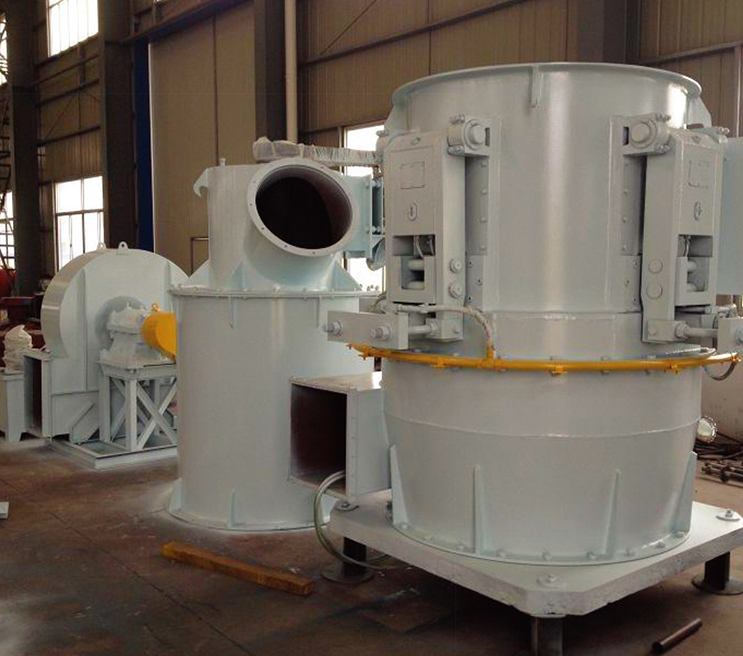
Wear parts matter too. Worn grinding rollers or rings generate a broader particle size distribution with more ultra-fines that are harder to capture. A mill that maintains tight control over product fineness—with a classifier that rejects oversized material efficiently—produces a more predictable dust stream. The result is a filter duty that is steady rather than spiking, which translates directly into longer bag life and lower emission variability. A processing line that pairs a well-maintained grinding mill with a right-sized baghouse typically records annual emission averages below 3 mg/Nm³, according to operating data from limestone grinding circuits producing D97 < 20 µm product.
A Step-by-Step Dust Control Audit for Your Powder Plant
An internal audit should take no more than two days and requires a pitot tube, a manometer, and a particle counter. The goal is not to replace a certified stack test but to identify the gaps that cause compliance failures. Following a structured sequence prevents the common mistake of fixing a symptom while ignoring the root cause.
- Map every fugitive emission point. Walk the entire circuit—feed bin, mill inlets and outlets, classifier connections, screw conveyors, bucket elevators, and packaging stations. Use a real-time dust monitor to log peak and average concentrations at operator breathing zones. A reading above 3 mg/m³ (respirable) indicates a capture deficiency.
- Measure the background concentration in the building. This establishes a baseline against which improvements are judged. In a well-controlled plant, total suspended particulate (TSP) inside the building stays below 1 mg/m³ outside process areas.
- Evaluate existing collector capacity. Calculate the actual air-to-cloth ratio by dividing the total airflow (m³/h) by the net filter area (m²). For mineral powders, this ratio should be between 1.0 and 1.5 m/min. If your ratio exceeds 1.8 m/min, the collector is undersized and will blow bags or emit at elevated levels.
- Compute the required filter area. Simple formula: Required area (m²) = total system airflow (m³/h) / (60 × desired filtration velocity in m/min). Compare this to the installed area. A 15,000 m³/h system aiming for 1.2 m/min needs 15,000/(60×1.2) = 208 m² of cloth. If the existing baghouse offers only 150 m², you need an expansion or a pre-separator.
- Draft a prioritized retrofit plan. Rank actions by cost-effectiveness: seal leaks first, then add local hoods, then upgrade filter media, and only as a last resort increase fan and collector size. Each step should include a responsible person, a target completion date, and a projected emission reduction.
Executing this audit annually, and after any major process change, keeps the plant ahead of both environmental regulators and catastrophic dust events.
Low-Cost Retrofits for Compliance-Ready Operations
Capital constraints should not block progress toward compliance. Three targeted interventions, each achievable with a modest budget, can close the gap between a dusty plant and one that passes a spot inspection. These retrofits focus on containment, filtration efficiency, and real-time awareness.
- Seal enclosures and local hoods (one-time cost under $5,000). Install flexible rubber skirting at belt transfer points, seal inspection doors with neoprene gaskets, and add a simple sheet-metal capture hood over the mill feed chute. A 4-inch-diameter flexible duct connected to an existing baghouse branch can pull 300–400 m³/h from a hopper opening and eliminate the visible plume that triggers complaints. The payback in reduced housekeeping labor alone is often under six months.
- Upgrade filter bags to PTFE membrane media (incremental cost $15–25 per bag). Standard polyester felt achieves about 99.9% efficiency. A PTFE-laminated felt raises that to 99.99% and resists sticky dust adhesion. The surface filtration mechanism also lowers the pressure drop by 200–400 Pa, cutting fan energy by 5–10%. For a 200-bag collector, the added investment of roughly $4,000 can pay back within two years through lower electricity and longer intervals between bag changes.
- Add differential pressure monitoring with alarm output (cost $1,500–$3,000). A simple DP transmitter connected to a local display and a PLC input provides immediate warning when the pressure drop exceeds the clean-bag baseline by more than 500 Pa. This single sensor prevents the majority of catastrophic bag failures because operators receive an alert before the pressure spike turns into a tear. The data can also be exported to the plant’s historian, satisfying the maintenance log requirement.
When combined, these three modifications create a defense-in-depth that moves a plant from reactive dust control to proactive compliance without a major capital project.
Maintenance Documentation: The Key to Proving Compliance
An inspector’s first request is rarely to see the stack. They ask for the records. A well-organized maintenance log that shows pressure-drop trends, bag change dates, and quarterly emission test results transforms a compliance audit from an adversarial interrogation into a formality. The documentation must prove not just that the equipment was installed, but that it is continuously managed.
A digital log generated by the process control system is ideal. For plants using a PLC-based controller, a Siemens S7-200 PLC can record and timestamp every relevant parameter, then compile a monthly summary report. If a PLC is not available, a paper logbook with the following fields, checked at the start and end of each shift, is acceptable:
- Date and shift supervisor signature
- Baghouse differential pressure (start of shift and end of shift)
- Pulse cleaning cycle interval (in seconds) and compressed air pressure (bar)
- Fan motor current draw (amps)
- Visible emissions observation at the stack (clear, light haze, or dense plume)
- Date and details of any filter bag replacement, including bag location and brand
- Last recorded quarterly emission test result (mg/Nm³)
Maintaining these records for at least three years satisfies most North American and European regulatory requirements. When a regulator can flip through months of stable pressure-drop curves and see a gradually decreasing emission trend, the “compliance-ready” status becomes self-evident.
EPCM Integration: Why System-Level Design Matters for Compliance
Purchasing a high-efficiency baghouse and connecting it to a mill bought from a different vendor may seem cost-effective. In practice, it creates an accountability gap. The mill manufacturer guarantees grinding performance, the filter supplier guarantees emissions, but no single party guarantees that the airflow, duct velocities, and pressure drops between them create a balanced, compliant system. This is where an EPCM (Engineering, Procurement, Construction Management) approach pays off.
An integrated EPCM partner sizes the exhaust fan to overcome the combined resistance of the mill, ductwork, cyclone pre-separator, baghouse, and stack—a total system pressure drop that can exceed 4000 Pa. A turnkey EPCM project for powder grinding also ensures that the explosion isolation design (such as flameless venting on the baghouse and an isolation valve on the dirty air duct) meets NFPA 654. Without this integration, a plant may discover during commissioning that the fan is too small, the conveying velocity is too low, or the ductwork collapses under negative pressure.
Case data from recent limestone grinding line deliveries demonstrates the difference. When a complete circuit—vertical ring roller mill, dynamic classifier, baghouse, and 3500 m³/h fan—was designed as one system, the stack emission measured 2.4 mg/Nm³ during the performance test. At a similar plant where the baghouse was added later to an existing mill, emissions fluctuated between 9 and 15 mg/Nm³ for six months until duct modifications were completed. Compliance is a system property, not a component specification.

 Email:
  Telephone: +86-13951382065
 Phone: +86-13951382065